Basic Verilog
Jeremy Bennett
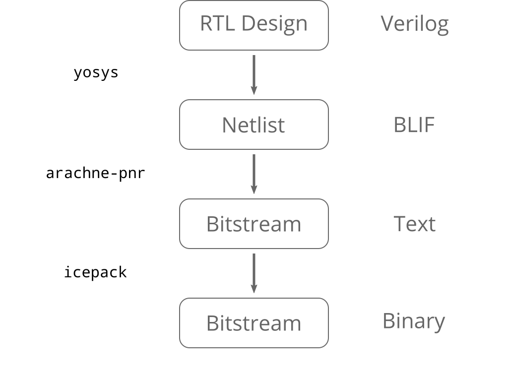
Designing individual gates and flip-flops is possible, but infeasible on huge modern chips. Instead:
We will use Verilog to describe this. It provides
This continuously assigns the value 1 to the LED pin:
module led (output led);

   assign led = 1;

endmodule
But how does this understand that led is connected to the LED?
The module declaration tells us about all our input and output signals:
module chip (
    // 100MHz clock input
    input  clk,
    // SRAM Memory lines
    output [18:0] ADR,
    output [15:0] DAT,
    output RAMOE,
    output RAMWE,
    output RAMCS,
    // All PMOD outputs
    output [55:0] PMOD,
    input [1:0] BUT
  );
We can use continuous assignment to set signals we don't want to use:
// SRAM signals are not use in this design, lets set them to default values
assign ADR[18:0] = {19{1'b0}};
assign DAT[15:0] = {16{1'b0}};
assign RAMOE = 1'b1;
assign RAMWE = 1'b1;
assign RAMCS = 1'b1;

// Set unused pmod pins to default
assign UART_TX = PMOD[11];
assign PMOD[54:12] = {42{1'b0}};
assign PMOD[10:00] = {11{1'b0}};
And finally we instantiate an instance of the led module inside the
chip module.
  led my_led (
    .led (PMOD[55])
  );

endmodule
PMOD[55] is the external pin corresponding to the red LED. But how does
Verilog know that?
The file blackice.pcf maps the named top level ports to actual pin
numbers on the FPGA:
#pmod 1
set_io PMOD[0] 94 # rd6
set_io PMOD[1] 91 # rd4
set_io PMOD[2] 88 # rd2
set_io PMOD[3] 85 # rd0
...
#pmod 14 SPI muxed with leds
set_io PMOD[52] 71 #LD4,!SS,p14_1
set_io PMOD[53] 67 #LD3,MISO,p14_2
set_io PMOD[54] 68 #LD2,MOSI,p14_3
set_io PMOD[55] 70 #LD1,SCL,p14_4
# SRAM
set_io ADR[0] 137
set_io ADR[1] 138
set_io ADR[2] 139
...
# Onboard 12Mhz oscillator
set_io clk 129

# Buttons
set_io BUT[0] 63
set_io BUT[1] 64
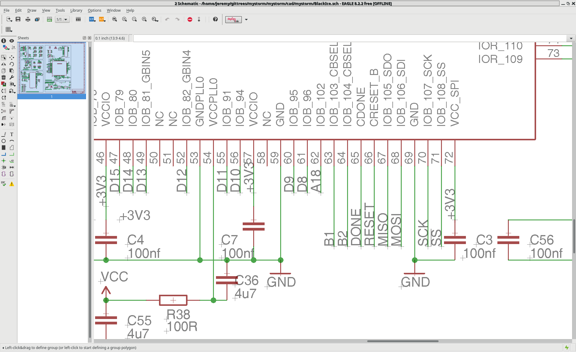
But where do you find the pin numbers?
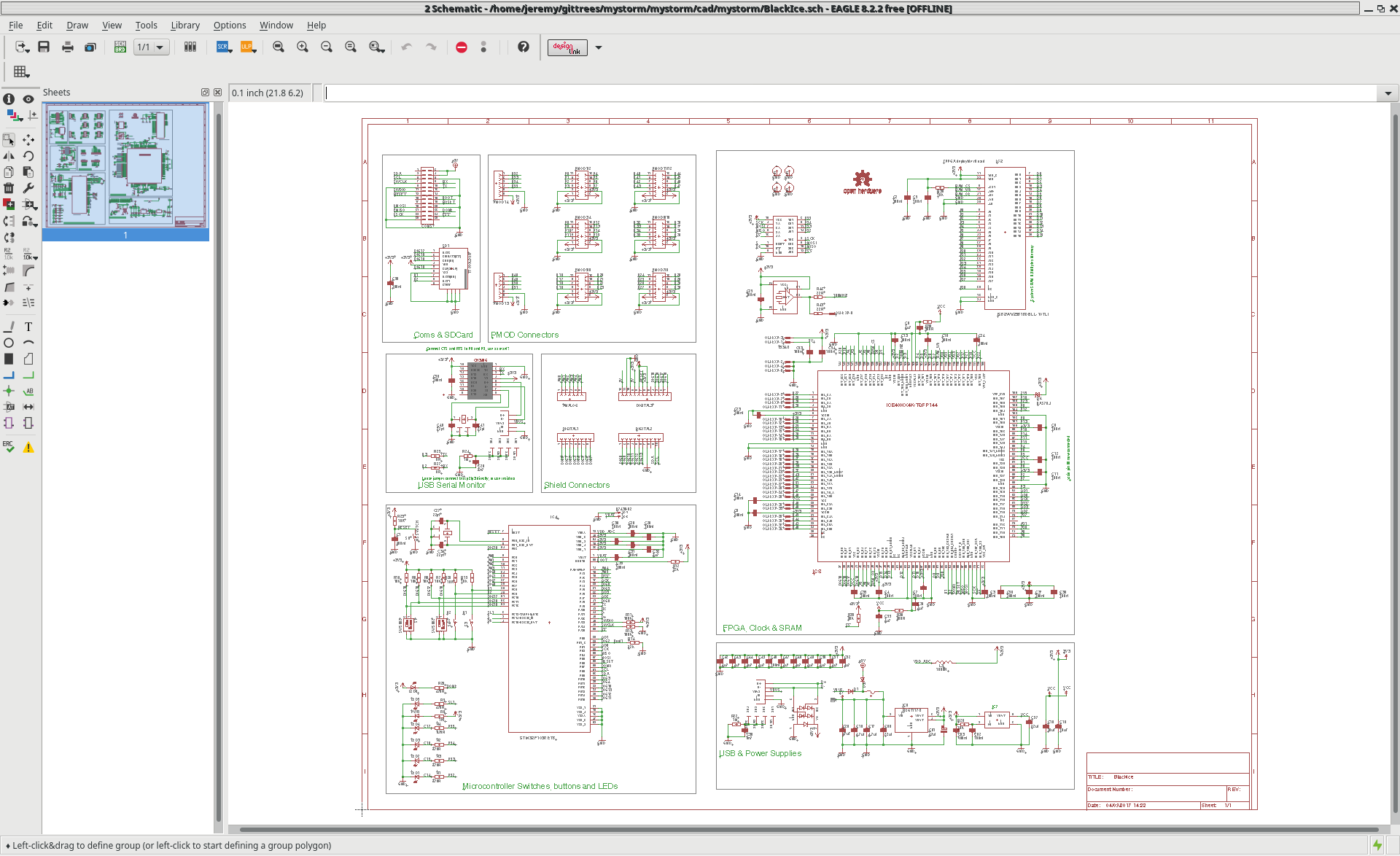
MyStorm repository, BlackIce branch, in the cad/mystorm directory.
Start with led.v in the basic_verilog/led directory. Complete it and
build it with:
make led
Then try the following changes:
led.v and chip.v to light one of the other LEDs.Next stage of the tutorial, we'll get the LED to change depending on which button is pressed.